CE-126P Hardware Info
First a warning:
Manipulating your CE-126P is at your own risk, there is no
warranty of any kind.
For some experiments a PC-1401 would be helpful.
Changing the 11 Pin Connection Cable
The cable was available as a spare part from sharp. This is
the pin numbering of the 11 pin connector at the left side of your
pocket computer:
+-------------
� on
1 --� +-+ +---------
2 --� � � �
3 --� +-+ � > LPRINT�
4 --� off � _ _
5 --� +-----------
6 --�
7 --� +---+ +---+ +---
8 --� +---+ +---+ +--
9 --� +---+ +---+ +-
10 --� +---+ +---+
11 --� +---+ +--
� +---+
The pins are assigned to the following wire colours:
|
Pin Number
|
Colour
|
Pin Number on the CE-126P PCB
|
|
1
|
light blue
|
C
|
|
2
|
pink
|
J
|
|
3
|
grey
|
A
|
|
4
|
black
|
H
|
|
5
|
white
|
I
|
|
6
|
blue
|
B
|
|
7
|
violet
|
K
|
|
8
|
yellow
|
D
|
|
9
|
orange
|
E
|
|
10
|
brown
|
F
|
|
11
|
red
|
G
|
To open your CE-126P remove the paper, the transparent cover
where the paper is inside and the batteries. Now remove the two
visible screws at the backside and the two screws inside the
battery case. The two parts of the case may now be taken apart,
but be careful, they are connected with some wires. Inside the
CE-126P, where the cable is connected it looks like this:
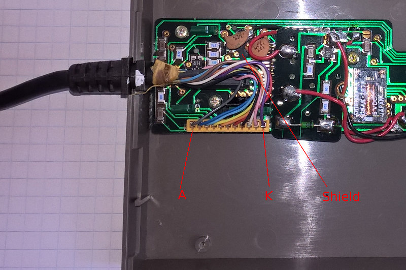
I have labelled the pins on the PCB A to K.
The assignment to the wires is shown in the table above. Note that
pin order is not the same as on the 11 pin connector on the
pocket computer. The shield is connected on a soldering point
between two brown ceramic caps (another black wire goes from this
soldering point to the second PCB inside the CE-126P).
Adjusting the Thermo Printer Temperature
There is an adjustable resistor (20000 Ohm) on the PCB beside
the battery case. With this resistor you can adjust the print
quality between light grey to black. Be aware that turning the
resistor to strong black may damage the thermo printer or consume
your batteries very fast.
Using Accumulators
If you use NiCd accumulators, you may want to load them
inside the CE-126P with an DC adaptor. The CE-126P has
the ability to do this. Take your CE-126P apart like described
above. At the backside of the battery case there are two small plates
connected to red wires. If you connect them together, the
accumulators will be loaded. Warning: From now on, don't
use batteries, they are not built for recharging and may explode.
Extra Characters
There are some extra characters, which are not printable
with LPRINT. They have the code 1 - 12, 21 - 31 and
254 - 255. Here is a little program for the PC-1401 which lists
all the extra characters: xtrachar.bas
The trick is, that the character code is poked to the standard
variable D$ and then lprinted to the CE-126P. Here
you can see, what the extra characters look like:
xtrachar.tif
Controlling the Remote Relay
If you want to do this with your PC-1401, you first have to
know if your computer has the old or the new ROM version. To check
this is rather simple: If you have the old ROM, the factorial of
a number is calculated with e.g. FAC 3, if you have
the new ROM, FACT 3 will work. Here are the call
addresses:
|
|
Old ROM
|
New ROM
|
|
Relay ON
|
CALL 43007
|
CALL 43107
|
|
Relay OFF
|
CALL 43008
|
CALL 43108
|
Note, that I was only able to check the new call addresses,
because my PC-1401 has the new ROM version.
Character Table
Here is a little program for the PC-1401 which prints a
character table (Including the extra characters). Again, you
have to know if your PC-1401 has the old or the new ROM.
The program contains two short machine language programs
and uses the system call CALL &A984
(CALL &A920 for old ROM) which prints a line.
Here you can see, what the character table looks like:
ctable.tif
Emulating the CE-126P with an Arduino board
Cavefischer has some interesting Arduino based projects for emulation of the CE-126P with an Arduino board (in german).