|
Sharp Pocket Computer - Serial Interface
|
Universal Serial Interface for Sharp Pocket Computers
Universal Serial Interface for Sharp Pocket Computers
Introduction
First a warning:
Building and using this interface is on your own risk, there is no
warranty of any kind.
And now, lets start:
This article enables you to construct a serial interface for all sharp
computers with the 11 pin peripheral interface or the 15 pin serial interface.
The interface performs a level conversion any has various jumpers to configure
it for the use with your pocket computer and transmission software. The
purpose of the device is to link your pocket computer to the serial port
of your personal computer. There are different software products you can
use on the personal computer side:
Standard Terminal Program
Terminals like Teraterm, Minicom, Seyon and Hyperterminal may be used for
all pockets with the 15 pin serial interface (PC-1350, PC-1360, PC-E500(S)
...). Just set the com parameters to the same values on the pocket and
on the PC. The programs are transferred in ASCII format. When downloading
files to the pocket, you usually have to type a
Ctrl-Z
after end
of transmission to get the basic prompt again.
Beside this, there are many transfer programs for the serial ASCII transfer
over the 15 pin peripheral interface, e.g.
from Simon Lehmayr.
The PC-E220 is also able to work with a Standard Terminal Program, but
this model has it's serial interface integrated into the 11 pin peripheral
port. The power supply may be remote controlled from pin 5 of the peripheral
interface, so you don't need to use a power switch for the universal serial
interface circuit. I think, the PC-E220 has the best serial interface,
because
-
it uses a simple 2,54 mm pinhead
-
the big AA-batteries of the pocket may be used for the interface supply
too
-
the supply may be remote controlled.
The PC-1403(H) is able to to work with a standard terminal program if a
driver (machine language) is installed into the pocket. There are two drivers
available for the PC-1403(H):
-
PETOOLS 1.1 has a integrated serial port driver (will be released soon
on this site)
-
The was an article in the C'T magazine (Go to www.heise.de
and search the article archive for C'T 1989, number 3. The title (in german)
is "Tore zur Welt"). The
![[BROKEN]](images/brokenlink.gif) SHARP Pocketcomputer Seite von Jerry C has also published a page that with a
home made serial interface based on this article. SHARP Pocketcomputer Seite von Jerry C has also published a page that with a
home made serial interface based on this article.
On a PC-1403(H) with PETOOLS 1.1 (or higher), the programs are transferred
in ASCII mode, but you need a (de)tokenizer on the host PC to convert the
basic tokens to/from ASCII. Maybe I'll publish one with PETOOLS 1.1. If
you use the software published in C'T, you don't need a (de)tokenizer,
but this software can't handle some basic commands like "XOR". The software
from C'T is also available for the PC-1401/1402, but I didn't check this
out.
The advantage of using a standard terminal is that it is platform independent,
the files are transferred in ASCII mode and you don't need to switch to
DOS mode. The transfer rate is up to 9600 bd (CLOAD/CSAVE: less than 500
bd).
FAZ' Software
This software is available from FAZ'homepage. It emulates a tape drive, you can use CLOAD, CSAVE
and MERGE (and maybe INPUT# and PRINT#).Should work for all pockets except
the PC-Exxx series. You may backup the content of your pocket with it,
but there is no converter to/from ASCII format. Should run in DOS mode,
source code is included.
Friedi's Software
Available from ![[BROKEN]](images/brokenlink.gif) SHARP PC-1403(H) Resourcen, runs in DOS mode. Also emulates a tape drive, you can use CLOAD,
CSAVE and MERGE. The models PC-1251, PC-1262 and PC-1403(H) are supported.
A (de)tokenizer is included. There is a sharp printer emulation included,
it worked for LPRINT and P <-> NP, but not for LLIST. To have a better
screen layout, just type the following before starting Friedi's software: SHARP PC-1403(H) Resourcen, runs in DOS mode. Also emulates a tape drive, you can use CLOAD,
CSAVE and MERGE. The models PC-1251, PC-1262 and PC-1403(H) are supported.
A (de)tokenizer is included. There is a sharp printer emulation included,
it worked for LPRINT and P <-> NP, but not for LLIST. To have a better
screen layout, just type the following before starting Friedi's software:
mode con codepage prepare=((437) C:\WINDOWS\COMMAND\ega.cpi)
mode con codepage select=437
Hardware
The hardware consists of the interface board, cable A for all pockets with
the 11 pin peripheral interface and cable B for all pockets with the 15
pin serial interface. The pins of the pockets are numbered as follows (e.g.
PC-1360):
    +-------------------------------------------------------------------------+
    |            PC-1360                                                      |
 1 -+                                                                         +-  1
 2 -+                                                                         +-  2
 3 -+                                                                         +-  3
 4 -+                                                                         +-  4
 5 -+                                                                         +-  5
 6 -+                                                                         +-  6
 7 -+                                                                         +-  7
 8 -+                                                                         +-  8
 9 -+                                                                         +-  9
10 -+                                                                         +- 10
11 -+                                                                         +- 11
    |                                                                         +- 12
    |                                                                         +- 13
    |                                                                         +- 14
    |                                                                         +- 15
    |                                                                         |
    +-------------------------------------------------------------------------+
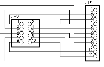
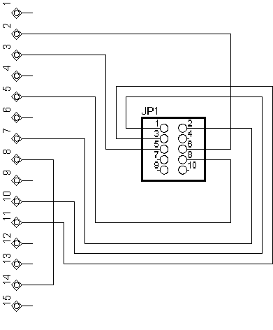
Pin Assignment between Cable A, Cable B and the
2 x 5 Pinhead of the interface board
|
2 x 5 pinhead
|
Cable A (11 pin)
|
Cable B (15 pin)
|
|
1
|
2
|
10
|
|
2
|
3
|
7
|
|
3
|
4
|
11
|
|
4
|
5
|
-
|
|
5
|
6
|
3
|
|
6
|
7
|
2
|
|
7
|
8
|
-
|
|
8
|
9
|
5
|
|
9
|
10
|
-
|
|
10
|
11
|
-
|
Pin 8 and pin 14 of the 1,27 mm pinhead (15 pin) of cable B are connected
together. 1,27 mm pinheads are available at e.g. at Conrad electronic. If you want
to use the internal batteries of the pocket, you can mount a switch between pin 1
of the 2 x 5 pinhead and pin 10 of the pinhead of Cable B (15 pin). With Cable A,
this wouldn't make sense, because the widely used CR-2032 batteries would be
discharged very fast and the PC-E220 (which has AA-batteries) is able to remote
control the power supply.
The Interface Board 
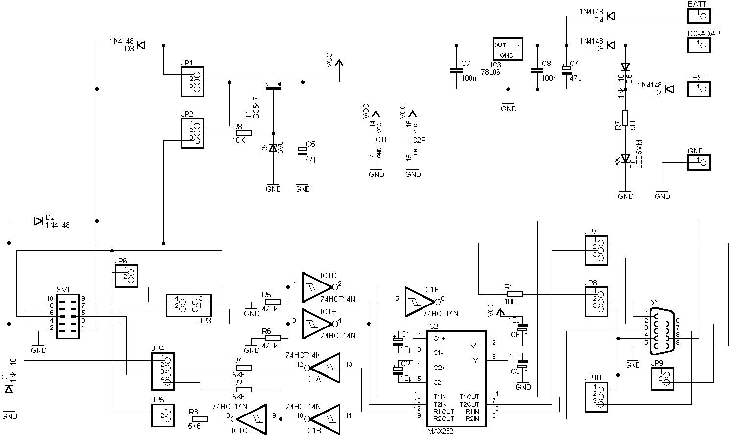
Yep, that's it. The parts should be available in every electronic store.
All resistors are 1/8 Watt, all electrolytic capacitors are specified with
16V. If you want to use a external battery, connect it between "BATT" (plus
pole) and "GND" (minus pole). If you want to use a DC adapter, connect
it between pin "DC-ADAP" and "GND". A 9V block would be suitable (put a
power switch between the plus pole of the battery and "BATT"). The 78L06
create a stable voltage of 6V. T1 reduces this voltage to an amount of
5V, it may be remote controlled from pin 4 (= pin 5 on cable A). LED D8
is on if the circuit is supplied from a DC adapter. If you use a battery,
you can solder a test button between pin "BATT" and "TEST". If it's pressed
the LED emits light.
For the first tests, I would do the following:
-
Use sockets for IC1 and IC2
-
Build up the circuit, but don't insert IC1 and IC2 and don't connect a
pocket or the PC
-
Connect a supply (DC adapter or ext. battery)
-
Check if JP1, pin 1 has 6V to GND (use a voltmeter)
-
Set a bridge JP1, pins 1&2 and JP2, pins 1&2
-
Now check the voltage on the sockets of IC1 and IC2 (IC1: 5V between pins
7&14, 14 is plus; IC2: 5V between pins 15 and 16, 16 is plus) The voltage
may be slightly over 5V, because the is no load and C5 may be loaded over
5V, but that is no problem
-
Now turn of the power, insert the integrated circuits and turn the power
on
-
Check the voltage on pin 2 of IC2 (about 10V to GND) and pin 6 of IC2 (about
-10V to GND)
-
Turn off the power, set the jumpers right for your needs, connect cable
A or B, the pocket and the PC and turn the power on again.
-
Ready to go!
Cable A 
Use a Plug suitable for the 2 x 5 pinheads, a ribbon cable a 2,54 mm
pinhead (11 pin). For my prototype, I used a small piece of experimental
PCB to connect the ribbon cable and the pinhead JP1. It is also possible
to create a small adapter PCB.
Cable B 
That's it. All wrote about cable A is also valid here (but you need
a 1,27 mm pinhead), and note the remarks made in the section Pin
Assignment between Cable A, Cable B and the 2 x 5 Pinhead of the interface
board. Phew, the small pinhead is very tricky to solder at a ribbon
cable!
PCB Developers Resources
If you want to create a PCB ... just do it, an send a mail with the result
to me :-) Here are the schematics. They were
drawn with Eagle 4.08r2, the electrical rule check gives only one warning
for the not connected pin 6 of IC1, so the creation of a PCB shouldn't
be a big problem. A light version (free for private use) is available
from www.cadsoft.de.
Description of the Jumpers
All pin numbers refer to the 11 pin peripheral interface, if you want to
know the pin numbers on cable B or the 2 x 5 pinhead, refer to Pin
Assignment between Cable A, Cable B and the 2 x 5 Pinhead of the interface
board. To get the pin numbers to the serial port signal names, just
look somewhere else on the net, e.g. ![[BROKEN]](images/brokenlink.gif) SHARP PC-1403(H) Resourcen has a description of the serial port pins. SHARP PC-1403(H) Resourcen has a description of the serial port pins.
|
Jumper
|
Description
|
Possible settings
|
|
JP1
|
Power supply
|
1-2 extern battery
2-3 internal battery of the pocket
|
|
JP2
|
Operate
|
1-2 always
2-3 remote controlled from pin 5 (for PC-E220)
|
|
JP3
|
Pin 4 & 7 configuration
|
1-3, 2-4 Pin 4 = CTS, Pin 7 = RXD/RI
1-2, 3-4 Pin 4 = RXD/RI, Pin 7 = CTS
1-3 Pin 4 n.c., Pin 7 RXD/RI
2-4 Pin 4 CTS, Pin 7 = n.c.
|
|
JP4
|
Pin 6 & 9 configuration
|
1-2, 3-4 Pin 6 = TXD, Pin 9 = RTS/DTR
2-3 Pin 6 RTS/DTR, Pin 9 = n.c.
3-4 Pin 6 TXD, Pin 9 = n.c.
|
|
JP5
|
Pin 8 configuration
|
closed Pin 8 = inverted TXD
open Pin 8 = n.c.
|
|
JP6
|
Pin 10 configuration
|
closed Pin 7 - Pin 10 loop back
open Pin 10 = n.c.
|
|
JP7
|
RI/RXD preselect
|
1-2 RI preselected
2-3 RXD preselected
|
|
JP8
|
DCD function
|
1-2 DCD = Pin 5
2-3 DCD - DTR loop back
open DCD = n.c.
|
|
JP9
|
DSR configuration
|
closed DSR - DTR loop back
open DSR = n.c.
|
|
JP10
|
RTS/DTR preselect
|
1-2 DTR preselected
2-3 RTS preselected
|
Operating the Interface
To connect the interface to your PC, you need a serial cable. One plug
is female and has 9 pins, the other is male and has also 9 pins. They are
connected 1:1. Such a cable is available in most computer shops for about
3 EUR (bucks?).
Jumper Settings for the universal serial Interface for Sharp Pocket Computers
|
Power supply
|
JP1
|
|
External
|
1-2
|
|
Internal from pocket computer 1)
|
2-3
|
|
Pocket Computer
|
Cable
|
Software
|
JP2
|
JP3
|
JP4
|
JP5
|
JP6
|
JP7
|
JP8
|
JP9
|
JP10
|
|
PC-E220
|
A
|
Standard terminal
|
2-32)
|
1-3, 2-4
|
1-2, 3-4
|
open
|
open
|
2-3
|
open
|
closed
|
2-3
|
|
PC-1251, PC-1262, PC-1403(H)
|
A
|
Friedi's Software
|
1-2
|
1-3, 2-4
|
1-2, 3-4
|
open
|
closed
|
1-2
|
1-2
|
open
|
2-3
|
|
Most pockets except PC-Exxx
|
A
|
FAZ' Software
|
1-2
|
1-3
|
3-4
|
open
|
open
|
2-3
|
open
|
open
|
open
|
|
PC-1403(H)
|
A
|
Standard terminal + PETOOLS 1.13)
|
1-2
|
1-2, 3-4
|
2-3
|
closed
|
open
|
2-3
|
2-3
|
closed
|
1-2
|
|
PC-1350, PC-1360, PC-E500(S)4)
|
B
|
Standard terminal
|
1-2
|
1-3, 2-4
|
1-2, 3-4
|
open
|
open
|
2-3
|
open
|
closed
|
2-3
|
|
PC-1401, PC-14025)
|
A
|
Standard terminal + Software from C'T (www.heise.de)
|
1-2
|
1-2, 3-4
|
2-3
|
closed
|
open
|
2-3
|
2-3
|
closed
|
1-2
|
Now have fun with your interface!
1) Only recommended for models which have AA or AAA batteries
(no lithium button cells), e.g. PC-E220 and PC-E500(S)
2) The PC-E220 model turns the supply of the interface on
or off by using pin 5 of the 11 pin interface, if JP2 is set to 2-3
3) or higher, ore use the software published in C'T (www.heise.de)
4) or other pockets with 15 pin serial interface
5) I have not tested it with the PC-1402 until now
|
|
|

