Sharp Pocket Computer PC-1251 Resource Page
Should also work for the PC-1250.
Note: The PC-1251 was also sold as "Radio Shack TRS-80 PC-3" (in the
united states, I think).
Books and Online Documentation
-
The "Pocket Computer PC-3 Operations Manual" (same as PC-1251) is available from
![[BROKEN]](images/brokenlink.gif) TRS 80 Hardware Manual Download Page.
TRS 80 Hardware Manual Download Page.
-
The book "Pocket Computer Programs" is available from TRS 80 Software Manual Download Page.
-
Historic Computing: Let's see: A MCS48 assembler listing (comments in german) for the emulation of a CE 125 printer
for the PC-1245 (but should work also for other PC-12XX models). Maybe I will dig out my MCS48 evaluation board ...
Maybe it is easy to port to a modern AVR controller ... Unfortunately the link is broken, but the Computer Cabinett Göttingen
gave me the permission to publish the file here.
For manuals and documentation related to Sharp pocket computers in general also have a look at the Documentation Section.
Calls to the System ROM
|
Command
|
Description
|
|
CALL 53
|
Turns the pocket computer off. Warning: If you use this, turn your
PC on with the BREAK Button (Don't use the sliding switch, or the whole
memory will be deleted)
|
|
CALL 4576
|
Turns the display on
|
|
POKE 50905,0
|
Turns the password protection off
|
|
POKE 50905,32
|
Turns the password protection on
|
Memory map
|
|
PC-1245/50
|
PC-1251
|
PC-1255
|
PC-1260
|
PC-1261/62
|
|
Inner CPU ROM
|
&0000 - &1FFF
|
|
ROM
|
&4000 - &7FFF
|
&8000 - &FFFF
|
|
RAM
|
&C000-&C7FF
|
&B800-&C7FF
|
&A000-&C7FF
|
&5800-&67FF
|
&4000-&67FF
|
|
Video RAM
|
&F800-&F87F
|
&2000-&287F
|
There are some very nice memory maps also on
Yagshi's page.
Accessing the display
Even the display is very small (5x7x24), you can access every block on
the display, and very confusing, the special functions display. Here are
the pokes for the special function display:
|
POKE &F83C,X
|
|
1
|
DEF
|
|
2
|
P
|
|
4
|
G
|
|
8
|
DE
|
|
16
|
-
|
|
32
|
-
|
|
64
|
-
|
|
128
|
-
|
|
|
POKE &F83D,X
|
|
1
|
BUSY
|
|
2
|
SHIFT
|
|
4
|
RAD
|
|
8
|
E
|
|
16
|
-
|
|
32
|
-
|
|
64
|
-
|
|
128
|
-
|
|
|
Remember, that switching the display may activate the corresponding mode
e.g. switching "RAD" on will cause "SIN", "COS" and "TAN" to calculate
in RAD-mode.
To access the display blocks just do the following:
-
Erase the display:
WAIT 0:PRINT " "
-
Turn the display on:
CALL 4576
-
Write to the display memory:
POKE Addr,Pattern
The display columns have addresses as shown in the table below:
�
|
Characters pos. 1-12
|
Characters pos. 13-24
|
|
|
|
As you can see, the display is divided into two block, the first on
is addressed bottom up, the second one top down.
Calculating the column pattern:
�
|
The pattern is calculated by adding the value of every pixel you want
to display in black together, e.g. the second column in the picture at
the right side would be 4+32+64=100. If you want to display the figure
at the right side at character position 1, you would use
POKE &F800,2,100,29,100,2
If you want to display the figure at the right side at character position
10, you would use
POKE &F832,2,100,29,100,2
|
|
If you want to keep the display stable for a while, just insert a waiting
loop:
FOR I=0 TO 200:NEXT I
Like most of the Sharp pocket computers, the PC-1251 also has some nasty
side effects at the right side of the display while doing direct access
to the display memory. This can only prevented by writing a machine language
program.
Here's an example which fills the display from the left to the right
with black columns:
10 CALL 4576:REM DISPLAY ON
20 FOR I=0 TO &3B
30 POKE &F800+I,&FF
40 NEXT I
50 FOR I=&7B TO &40 STEP -1
60 POKE &F800+I,&FF
70 NEXT I
Programs
Have a look at the PC-1251 File Archive.
To avoid mini keyboard typing, first have a look at Tools to link your pocket computer to your big PC.
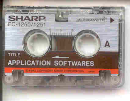
Application Tapes
|
Note that it's only allowed to download the content of the tapes if
you own the original tape (or you think you did own it in the past...).
I'm publishing this because the PC-1251 is now an obsolete computer. If
someone doesn't like this to be published here, he can tell me and I'll
remove it immediately.
I have extracted the files from the application tape shown below.
The content is not complete, because the tape drive
from my CE-125 or the application tape are gone forever while restoring
the tape. I don't know what this software is good for, maybe it's only
usable with a manual (which I don't own). Enough words, you can download
the zipped content from here. The
numbers in the filenames refer to the tape counter at the start of the file.
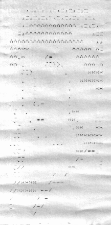
Michel Jubault has contributes an application tape. It contains the same
files as the tape mentioned before (the are some small differences, maybe
it's an older/newer version). It's complete and you can download it
here. I have made a hardcopy
of the "portrait" program output, as you see on the right side
of this page (cool ascii art, isn't it?).
 I converted an applikation tape which was included in a
PC-1251/CE-125 set I got from ebay. The content of the application tape
are programs to calculate the size of heating systems (size of radiators
or something like that). The program interface and the documentation is
in german. You can download it here. I converted an applikation tape which was included in a
PC-1251/CE-125 set I got from ebay. The content of the application tape
are programs to calculate the size of heating systems (size of radiators
or something like that). The program interface and the documentation is
in german. You can download it here.

|
|
Memory Extension
Adam Roman wrote me an email about his memory extension of a PC-1251. I did not try this. If you try it, you do it at your own risk (as allways ...)
Edgar,

Just wanted to let you know that I found your info on the PC-1251 (and links to memory maps) Very
useful.  With that info available, I decided to try something.

Once I figured out the complete pinouts of the memory board, I was able to expand the RAM of my
PC-3 to a full 18K!!  The MEM command gives back 17822 after a reset.  Apparently, my RAM goes
from 0x8000 to 0xC800.  The OS RAM search must start at 0xC800 and work backwards until it hits ROM.
(This is evident in the PC-1255 memory map.)

The memory was connected by removing both 2K x 8 SRAMs, and replacing them with a single 32K x 8 SRAM,
with several pins lifted up and wired to pins on the ROM.  A0 - A14 are connected directly, and
the chip select line is an inverted A15 (thru an added 4069 inverter).  The 2 chip selects from
the processor appear to be hardwired on 2K boundaries.  (Only 2K showed up until !A15 was used as
the !CS.  There is no apparent conflict for any overlapping addresses.  I believe the bus is active
only for external accesses, not for internal VRAM, etc., from 0xC800 to 0xFFFF.)  !OE is grounded
as before.

I did the same thing to my PC-E500 years ago, but the SC62015 processor must have programmable chip
selects, since the existing !CS line auto-detected the 256K I had installed without any addressing
tricks.

Here are the pinouts for the memory card.  With the chips facing up and the connector on top, there
is the spring connector for ground on the left, then 27 connections in the middle, then the Vcc
spring on the right.  The 27 pins are, from left to right, R/!W, D7-D0, 2 chip selects, then
A15 to A0, with A0 on the right next to Vcc.

If you would like any other info, let me know.

Anyway, just thought I'd share.  Feel free to post this.  Thanks again!


Regards

Adam Roman
Adam Roman sent me an update to his memory extension (I still didn't try it):
Hi Edgar,

Thanks for posting the memory upgrade email.  It's been a while.  I didn't
know if your page was still active, so I did not send a very necessary
update to that information...  I'd be happy to rewrite the whole thing and
include pictures, but I'd need a few weeks, so I'll just give you the
correction now.

When looking at the memory board with the chips facing up and the
connections across the top, the 2K x 8 sram on the Left must be present, and
must be 2K.  This is the base 2K that is in the PC-1250, from 0xC000 to
0xC7FF.  The Right location has the second chip select, which the OS
auto-configures during initialization, and does add up to another 16K by
design, by properly adding a 32K sram with A14 tied low.  No other address
decoding is needed.  Other than getting a very low power 3.3V cmos sram
(>10uA sleep current) the only trick about it is that a 32K TSOP sram is a
larger 32-pin chip, and Sharp (undoubtedly anticipating the larger future
chips) made the casing so that a small plastic pin goes right where pins 31
and 32 of the 32K chip need to go, so that pin (and the adjacent plastic)
must be trimmed a bit, which is no problem.  The main reason the plastic is
there is to annoy people.

Sorry about the error, but I promise, this does work with no problems.  My
programs are still safe and sound (with the same batteries) after 2 years.

Regards

Adam Roman